| |
|
Website Position: Homepage  Products Active Balun Transceiver Single Channel Balun Transceiver Products Active Balun Transceiver Single Channel Balun Transceiver |
| |
 Single Channel Active Video Balun Transceiver ( CCTV via Unshield Twist Pair Cable) Single Channel Active Video Balun Transceiver ( CCTV via Unshield Twist Pair Cable) |
| |
|
BALUN Transceiver Product Catalog (PDF Download) 
|
|
|
|
| |
|
|
HT801AT -Mini Single CH Tx w/Slide Switch |
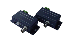
HT801ATR - Mini Single Transceiver |
|
|
HT801AR -Mini Rx w/Slide Swtich-Potentiometer |
HT801ATR - Mini Single Transceiver |
|
|
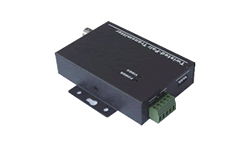
HT801BT- Single Channel Tx w/Code Switch |
HT801BT- Single CH Tx w/Code Switch |
|
|
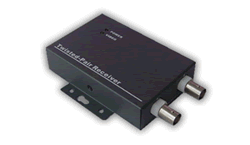
HT801BR - Single Channel Rx w/Code Switch |
HT801BR-2 - 1to2Port Rx w/Code Switch |
| |
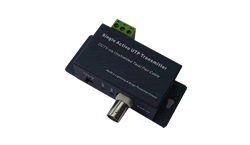
HT801AT Mini 1 CH Active UTP Video Transmitter
HT801BT Single Channel Active Video Transmitter
4000ft Video Transmission Distance +12V Power Supply GND Connect
Metal Housing Case Screw-BNC Terminals Gain/EQ Code Switch ADJ
HT801AR Mini 1 Channel Active Video Receiver
3 Step Slide Switch and Potentiometer for Gain/EQ Fine ADJ
HT801BR Single Channel Active Video Receiver
HT801BR-2 1-2 Single CH Active Video Receiver
'HUM-BARs' Rejective Video Transceiver with Gain/EQ Code Switch ADJ |
| |
|
|
| |
Video Balun Transceiver Instruction
|
HT801T and HT801R/HT801BR-2, the Single Channel CAT5 Video Transmitter and Receiver are an active (amplified) pair equipment that allows the extension of real-time monochrome or color video on up to 4000ft (with Image figure enhanced function), using Category-5 Unshielded Twisted-Pair (UTP) CAT5 networking wire. Composite Video Broadcasting Base band (composite-CVBS/AV, PAL/NTSC/SECAM) signals of any video type are supported.
The unparalleled interference rejection and low emissions of the transceiver allows long run video signals to co-exist in the same wire bundle as telephone, data-com, or low-voltage power circuits. This allows the use of shared or existing cable plant. Ground-lifting circuit design ensures no annoying "hum-bars" when ground potential differences exist.
Built-in lightning protection, transient protections, ESD protection, power line contact protection, damaging voltage spike problems are eliminated.
|
| |
Equipment Specifications
|
Cable Distance:Up to 4000ft Transmitter-Receive UTP Cat 5 or better.
Point to Point transmission of real-time PAL,NTSC or SECAM single channel CVBS video signals.
Image figure enhanced function in output of CAT5 video receiver.
Lightning protection, Transient protection, ESD protection, Power Line Contact protection, damaging voltage spike problems are eliminated.
Dimensions: 94X84X22mm, GND screw connector.
|
Technical Specifications |
-
Video Frequency Response:
DC to 6 MHz
-
DC Coupled Amplifier Mode
100V/us transient responding
-
Differential Gain: 0.5%
-
Differential Phase: 0.3°
-
Distance Switch 4-Position Adjustable for each channel.
-
Common-mode/Differential-mode Rejection:
15KHz to 5 MHz, 65 dB typical.
-
Channels Cross Talk: -68dB.
-
Loop Return Loss: over 15dB
-
Figure Enhanced Output:
4.43MHz extra emphasis
-
Line Impedance:
Coax, female BNC 75 ohms, CAT5 line, Terminal Block 100 ohms.
-
Wire Type: Network Wiring One Unshielded Twisted Pair 24-16 AWG (0.5-1.31mm).
Category Type Cat 5 or better. Impedance 100±20 ohms.
-
DC Loop Resistance 52ohms per 1,000 ft (18 ohms per 100m).
-
Differential Capacitance 19pF/ft max (62pF/m max).
-
LED Indicator: Power On Red Indicator LED Light, Video On Yellow Indicator LED light
-
Power Supply: +12VDC/200-500mA
|
| |
Environmental
Temperature -20°C to +65°C.
Humidity (non-condensing) 0 to 95%.
Transient Immunity
6,000 V 1.2μS x 50 μS per ANSI/IEEE 587 C62.41 B3.
3,000 V 8μS x 20 μS when ground screw terminal is bonded to earth-ground.
Equipment Installment
1: Put the video signals you need in the VIDEO IN/OUT of CAT5 Video Transceiver.
2: Put a twisted-pair in the VIDEO A, B screw terminals of CAT5 Video Transmitter and Receiver respectively.
3: Connect with the mains following instructions shown in the system configuration diagram or sketch map, make sure power supply in +12VDC.
4: Set the position of ADJ correctly according to the distance table in Transceiver.
5: ‘GND’ screw terminal is bonded to earth-ground.
6: After the five steps, the VIDEO Outputs of the Video Receiver/Hub is ready to work.
Check after Connection
1. Power On Red Indicator LED Light.,
2. Make sure that UTP wire and coaxial cable is correctly and firmly connected.
3. Make sure the ‘GND’ screw terminal is firmly connected to earth-ground.
Mechanical
Dimensions:94X84X22mm
Material: Metal housing case
Maintenance & Quality Guarantee
3 Year Warranty
|
| |
|
Distance ADJ Switches Table |
Video Transmitter Distance ADJ Switches
0-600m 600-900m 900-1400m>1400m
Video Receiver Distance ADJ Switches
0-300m 300-600m 600-1400m>1400m
|
Product Information & Application Diagram
|
|
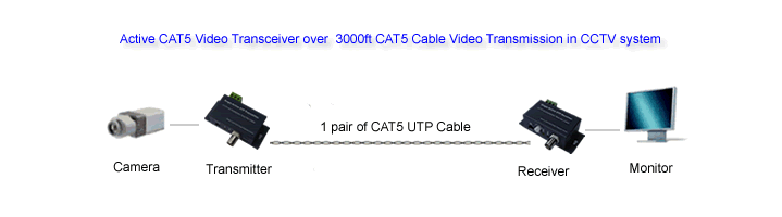
HT801ATR 1000m Distance UTP Cable Transmission CCTV System Configuration Diagram
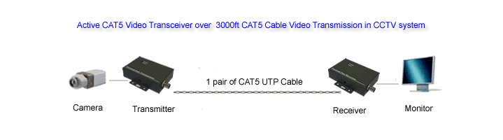
HT801BTR 1000m Distance UTP Cable Transmission CCTV System Configuration Diagram
|
|
|